Few days ago I was answering some questions to a project team and noticed the project has many openings using "Edit Profile" on a wall. I couldn't help but commented this was not a very efficient way to model opening in Revit.
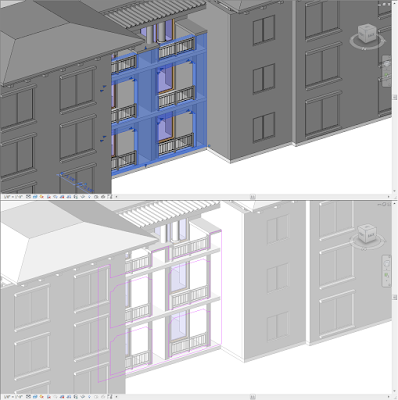 |
| Repetitive openings should be avoided using Edit Profile |
Typically there are 3 common ways to create wall openings in Revit. They are "Wall Opening" tool, "Edit Profile" and using family. In this post, I will explain some pros and cons on these tools and offer my perspective on the best practice when it comes to create openings.
Wall Opening Tool
The tool is under Architecture (Current version) or Home (prior 2014) tab --> Opening --> Wall. This is probably the easiest way to make opening in Revit. You pick your target (your wall) then define the area as a rectangle shape, Revit will make that opening for you. The upside is it is very easy to apply, very easy to make adjustment when needed. It can also be copied to multiple instances to the same wall. In addition, you can apply this in a curve wall too. So what's the limitation? There are some. This tool can only make rectangular shape. If you need anything other than that, you won't be able to do it at all. Autodesk, why can't you fix this already?
Edit Profile
This is also a native tool in Revit. You select any wall, the
"edit profile" icon will show up via the option bar. You can start
editing the shape of the wall in the "sketch mode"; make any changes
you need, then click the check icon to "finish". I often found many users
misuse this great tool in Revit and left with some unexpected result.
Cons:
If you use edit profile to make openings, they can't be copied. If
you need to "get rid" of the opening, you will have to activate the edit profile
and delete the sketch. Plus, it doesn't work on curve wall either. What if you
need to schedule the openings as "case opening" for your project?
Using this tool will not get you anywhere either. Another reason this tool bothers me so
much is that it is hard to tell if the opening is made using this tool.
Since you won't be able to "select" it like you would with "wall
opening" tool, sometimes it is very hard to locate them when the project
fully developed.
Using Family
This is probably my preferred method to make any openings in
Revit. The user creates a family (it can be wall hosted, face based or even
using the feature "cut void when loaded) usually by using void or "opening" to cut out the family host. You can then load it into the project and
cuts the wall with the family.
Why this is better? It really depends on what your purpose is, how
you create the family or how you use it. First of all, you will need to have the knowledge to build a proper family, in which case, it will probably be better if this is a parametric
family to be flexible to use it in project.
Using family has one advantage that the other two don't. Often times I have a
need in a project to make a recess (faux opening) in a wall, I could set a parameter to control
the void thickness, thus I can choose to cut the opening with different depth in a
wall. If you need the openings to be schedule in a project, this will be come in handy. Besides, you can copy multiple instances of the family on a fly in a project.
Cons:
If you don't know how to make a proper family, you would end up
having more issues using this method. Second, you would have to have different
families for different shapes (one for rectangular shape, one with an arch top,
etc...).
Conclusion
All of the above methods are valid ways to create openings, it is important to know the
differences between the pros and cons. What's more important is you should
stick with one method and keep it consistent throughout the project so the team
can have a better expectation.


