Showing posts with label Massing. Show all posts

Sunday, September 28, 2014

Divide Path Direction


I have questioned myself the logic when it comes to divide path in conceptual massing environment in the past. Recently I am working on an adaptive component for a panel where it requires a louver as part of the panel. I start with a 2 point adaptive family as a louver blade and nest it to the next family. The next family makes out of a set of reference lines and a frame, I have two edges that I use "Divide" to set up my "array".

I then place the blade family and try to use "Repeat" and lay out a series of blade.


It turns out the blade is going wild! At first I thought I have snapped my AC to the wrong node so it behaved unexpectedly.


After some trial and errors, I learn there is something I didn't realize before. For some reasons, when choosing an edge to divide path, one side of the edge has the node sequence backward; thus it results to an unpredictable array.

There is a hidden setting under the path properties. Select the path, check the "Show Node Numbers" and I am able to see the numbers on the path. Obviously they are going different direction.


The fix is quite easy. Check the box "Flip Direction" under the properties, it will set the path to the correct direction.


Try it again with Repeat and this time it works like a charm.


Sunday, October 13, 2013

Creating Roof Family for Folding Roof Planes

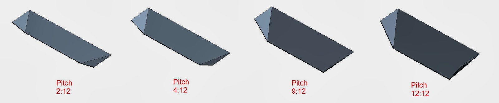
Not exactly. This is not a new family category in Revit where you can create a component family for the roof. However, one can actually create a mass family and use "Roof by Face" to achieve though.

I have a project where the design team came up with the roof design where two roof planes fold upward. Normally, I can use "roof by footprint" to create the roof. It is possible to do it but it can be tedious sometimes especially for those two end piece of the roof that folds upward. Since we are still studying the shape and want to explore with different roof pitch to get the best form. Trying to model the roof planes work together could be a time sink.


The team wanted to know if there is another way to do this more efficiently; so I thought I could make a mass family of the roof shape, set up a couple of parameters and we are in business!

Start making a mass family, I first lay out some reference points where I need to connect with model lines later. Once the points are set, create dimensions and set up parameters associated with those points.


Next, I use spline through points to create linear model lines (I later convert them into reference lines in the properties)  and get all the points connected.


I then select the reference lines and click "Create Form"; the forms are just surfaces that I need to use it to generate the roof once the mass family is loaded into the project.


Flex the family a few times to make sure the form follows with the parameters. One last thing I did before I loaded to the project was to add the formula to tie the "Height" parameter with the parameter "Roof Pitch". All that is done, it is good to go.


Load it to the project, offset it above the walls; I can use create "Roof by Face" to make these folding planes as a roof.


Since I made the mass family parametric, both the width and length are instance parameters, I can freely adjust the overall size of the roof form by pulling the shape handle. The nice thing about using mass family is that once the shape of the mass is changed, I can use "Update to Face" option to get the roof shape follows the new form as if I have a parametric roof family.


I can use the same mass family to generate the roof for multiple buildings in this project.


Saturday, September 28, 2013

Master Planning in Revit with Google Earth Image

We use sketchup a lot for conceptual design since it is fast and easy. Many designers in our office are so comfortable with the program. However, sketchup doesn't allow you to do any program area data and therefore, they often have to be manually done with excel or some other programs. It is time for a change.

We have a new project that is getting started in concept. We wanted to give it a shot and dive into Revit right from the start in programming. The team brought up a question and wonder if we can import a Google Earth image like we used to do in sketchup.

Google Earth image as background in sketchup
My immediate reaction was "Yes of course". I have played with an add-in from Revit in the previous version called "Acquire from Google Earth", you can import Google Earth image into Revit as well as publish Revit model to Google Earth. So I thought I would try it again in Revit 2014. The add-in tool is now updated called "Globe Link" (which can be downloaded from Autodesk subscription site); it does have the similar function like the early version in Revit.

After trying it again in Revit 2014, I ran into some error with the Google Earth. I found a blog post from the search that explained the compatibility issue between Revit and Google Earth and offered some resolution to fix that. I finally was able to get the site image imported to Revit. Nevertheless, the image only came in as a raster image that shows in plan view only. Not exactly what I want ...


I remember I did something similar in Vasari before. Vasari has a built-in function where you can bring in Google Earth image straight into Vasari and scale properly. It works seamlessly.


Why can't native Revit do this already!?
I thought I can save this as a .rvt file in Vasari then open it in Revit. I was happy for a moment and later realize it didn't quite work... Only an outline of the raster image showed up once the .rvt file opened in Revit.


Seems like this is another dead end to me. I thought there has to be a way to bring in just "an image" and use it in 3D view as backdrop. Then, a light bulb went off and it hit me. Why not use a decal?


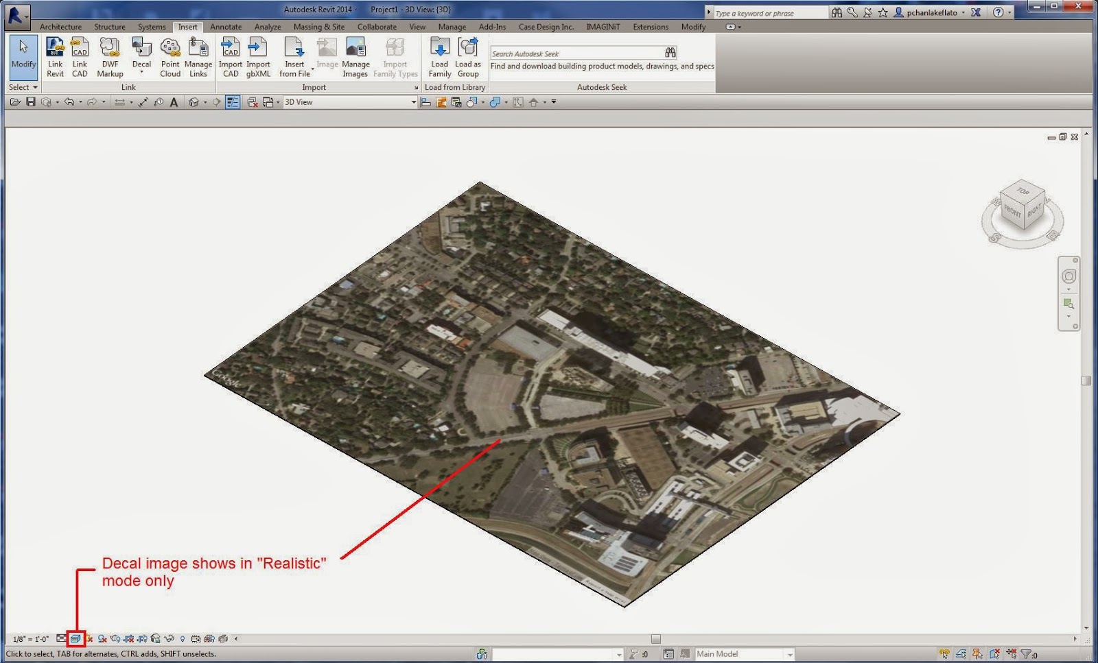
A decal in Revit will show up everywhere including 3D view. Go to Insert tab --> Decal --> Place Decal
Make a new type, load the image and place it!


In order to place the image as a decal, I need a "host" or a surface to place it. I made generic model family with a solid extrusion to host this image. You can also use other elements like a floor to do so. As for the sizing of the decal, I had to use a trick to get it scale properly. I actually used the Vasari file that I made earlier, I drew some model lines at the boundary of the image, copy the model lines to the clipboard, and then paste them into my site file. Now that I had the actual size of the boundary, I could use the same image export from Vasari and placed it as a decal.


Once I had the decal scale properly, I could now see it floating in 3D view, the only drawback was I had to switch it to "realistic mode" in order to see the Google Earth image.

Make some simple in-place masses for the surrounding buildings and the site is good to go! This workaround was to replicate what we like to achieve in Sketchup. By going through this process, it doesn't offer what the add-in "Globe Link" can do, which is to publish the Revit model back into Google Earth.


Saturday, September 14, 2013

Old Meets New - Massing with Old School Array

I was working on something in the past 2 weeks on massing. I have used a trick of nesting traditional Generic Model family into massing (or adaptive component) and pick the lines to create form or surface on many occasions. This time around, I thought of another way of using Generic Model again for something new.

First, I started off with a Generic Model template and draw a spline as a model line, I have the spline constrained to the parameter "H". During the RTC NA this year, I learned something new from Marcello Sgambelluri about scaling with a spline.


Next, I nest this model line spline into another Generic model and array it.


In this family, I set up the "Scale" and "Array" as an instance parameter where I can use it to nest into a massing family.


Start another family as a mass, load the GM array family. Draw an ellipse (actually two open-ended arch to form an ellipse); and have the nested array family locked to the end point of the arch. Add parameters to constrain the ellipse "Radius_Depth" and "Radius_Width". At the same time, associate the parameter "Scale" and "Array" from the nested family to the mass.


 Next, select the spline array from both ends and the arch; then hit "Create Form"...


I have made a ribbed surface. To my surprise, the surface is now driven by the spline. When I flex the parameter "Array", it will flex along nicely...


 I went and made another surface on the opposite side and form a complete mass.

 
Load the mass family into the project and start messing with the instance parameters...

First one with Array = 12, and Scale = 10 & 20 respectively.

Second one with Array = 20, and Scale = 2 & 20 respectively.

 Third one with Array = 36, and Scale = 10 & 30 respectively.

 I could go on and make more masses but I was pretty happy with this result for now...

Ribbed towers using nested array old tricks
I am now in the process of using this method to create something which I will post for next week, so stay tuned!