Wednesday, December 23, 2015

Season's Greetings from Phil-osophy in BIM!

What a busy year it has been! 2015 has almost come to an end.

Best wishes for joy and happiness this Holiday Season and a magnificent New Year!

Tuesday, November 24, 2015

AU 2015 Next Week!


Time surely flies! Autodesk University is just around the corner. I am very excited to be able to attend this conference again. This will be the first time since I joined HKS in January this year. We will have a big group from different locations representing the office to attend the event.

My colleague Tim Logan will present his class "Cross-Platform Plug-ins For Revit, Dynamo, and Beyond" that discusses his process of creating our in-house custom tool for Revit, Dynamo and Rhino.

Besides, I know there are a number of new techs such as Insight and Stingray from Autodesk that I am hoping to see first hand and meet up with the developers there.

I look forward to seeing some old friends and hope to make some new ones as well. Please be sure to say hello if you are going to be at AU.


Sunday, September 6, 2015

Open(ing) Sesame

Few days ago I was answering some questions to a project team and noticed the project has many openings using "Edit Profile" on a wall. I couldn't help but commented this was not a very efficient way to model opening in Revit.

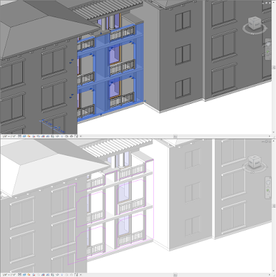
Repetitive openings should be avoided using Edit Profile


Typically there are 3 common ways to create wall openings in Revit. They are "Wall Opening" tool, "Edit Profile" and using family. In this post, I will explain some pros and cons on these tools and offer my perspective on the best practice when it comes to create openings.


Wall Opening Tool


The tool is under Architecture (Current version) or Home (prior 2014) tab --> Opening --> Wall. This is probably the easiest way to make opening in Revit. You pick your target (your wall) then define the area as a rectangle shape, Revit will make that opening for you. The upside is it is very easy to apply, very easy to make adjustment when needed. It can also be copied to multiple instances to the same wall. In addition, you can apply this in a curve wall too. So what's the limitation? There are some. This tool can only make rectangular shape. If you need anything other than that, you won't be able to do it at all. Autodesk, why can't you fix this already?


Edit Profile


This is also a native tool in Revit. You select any wall, the "edit profile" icon will show up via the option bar. You can start editing the shape of the wall in the "sketch mode"; make any changes you need, then click the check icon to "finish". I often found many users misuse this great tool in Revit and left with some unexpected result.

Cons:

If you use edit profile to make openings, they can't be copied. If you need to "get rid" of the opening, you will have to activate the edit profile and delete the sketch. Plus, it doesn't work on curve wall either. What if you need to schedule the openings as "case opening" for your project? Using this tool will not get you anywhere either. Another reason this tool bothers me so much is that it is hard to tell if the opening is made using this tool. Since you won't be able to "select" it like you would with "wall opening" tool, sometimes it is very hard to locate them when the project fully developed.


Using Family


This is probably my preferred method to make any openings in Revit. The user creates a family (it can be wall hosted, face based or even using the feature "cut void when loaded) usually by using void or "opening" to cut out the family host. You can then load it into the project and cuts the wall with the family.

Why this is better? It really depends on what your purpose is, how you create the family or how you use it. First of all, you will need to have the knowledge to build a proper family, in which case, it will probably be better if this is a parametric family to be flexible to use it in project.

Using family has one advantage that the other two don't. Often times I have a need in a project to make a recess (faux opening) in a wall, I could set a parameter to control the void thickness, thus I can choose to cut the opening with different depth in a wall. If you need the openings to be schedule in a project, this will be come in handy. Besides, you can copy multiple instances of the family on a fly in a project.


Cons:

If you don't know how to make a proper family, you would end up having more issues using this method. Second, you would have to have different families for different shapes (one for rectangular shape, one with an arch top, etc...).

Conclusion

All of the above methods are valid ways to create openings, it is important to know the differences between the pros and cons. What's more important is you should stick with one method and keep it consistent throughout the project so the team can have a better expectation.

Monday, August 31, 2015

No Strings on Me!

Recently I am working on making some changes on an existing family and notice there is a string of parameter that is "stuck"


For some reason, this parameter "Rough Width" in the family cannot be deleted. I have seen this in the past and one of the reasons has to do with the family has been upgraded year after year.

Question is "How do we get rid of this parameter?"

First, add a new reference plane on the side like the image.


Then, select the parameter and choose "Edit Witness Lines" from the option.


Have the dimension string snapped to the new reference plane, then select the reference to remove from the original location.


Once this is done, go ahead and delete the ref. plane. Without the ref. plane, the dimension string will be deleted.


This little trick can work on pre-existing parameter from the family template such as casework, baluster and window (wall hosted) family.


Sunday, July 12, 2015

Printing Bug

I came across with this issue from one user the other day. They have some interior elevations on the sheet that didn't come out as expected.


After printing it as PDF file, one of the interior views just showed up blank! What's interesting is the texts and grid lines showed but everything else disappeared.


I ended up reaching out to Autodesk and they suggested to try Raster Processing; and sure it did the trick. Using Raster Processing mode in the Print Setup was able to fix this issue. Usually raster mode is not needed unless you are printing with shadows, decal images or have render view as part of the document. This is one of the situations that this sheet had no such thing but will need raster mode to address the issue. 

You can learn more about Vector Processing vs. Raster Processing from Autodesk HERE.


Friday, June 12, 2015

Wall by Face - Part 2. Creating a Slanted Wall Tool

Taking the same idea from the wall-by-face by using generic model family. This time I am tying to explore the possible use of making a generic line based family. I have come across many times Revit does not have a slanted wall tool after all these years. Even Structural column has a slanted column option many versions ago. Why can't we have that tool? Is that really hard to make this as an enhancement in Revit?

We have slanted column already, when will we have slanted wall tool?

So I tinker with this notion of making a slanted shape parametric line based family and use wall-by-face to generate the wall. Why line based family, you may ask? Line based family functions very much like drawing a wall with "Wall" tool. On the floor plan, you can pick two points to place this family much like drawing a wall.


The intent for the use of this "tool" is to allow user to create slanted wall without having the need to build a massing family in the first place. With the instance parameter "Angle" as well as "Height", one can use the same family with "wall-by-face" command to make the wall. 


**This is NOT massing family, I just apply the same material "Default Mass" to the generic family**


Any time you have to change the slope "Angle", all you have to do is to set a new angle parameter, then use "Update to Face" to adjust the wall. 


Inside the family, it is just a line based family with a parametric sweep geometry.


The sweep form is made out of a nested profile family with formula to drive the sweep. 


Set the formula inside the profile family so the form is controlled by "Angle" and "Height".

During the testing, I noticed there was a clean up (miter) issue when two walls are connected at angles that are not 90 degrees. 


I went back and add two sets of voids to the family and now I can adjust the end condition with a new parameter.


I thought it would be a good idea to have a curved version of the slanted wall tool as line based family, too. Autodesk, when will you grant us the wish of having a slanted wall tool?


Friday, May 22, 2015

Wall by Face via Generic Model Family

I learned something new yesterday from Brian Mackey in his monthly webinar "Revit Radio" with guys from CAD-1 so I thought I'd share it here. When dealing with non-vertical wall, you either have to model wall as in-place family or using massing and create Wall-by-Face. Either way is a valid method. What's new to me is that you can also use Wall-by-Face and pick a surface of a Generic Model family in a project and create a wall. This includes Adaptive Component created as generic model. This is such a good news to me. Why? Compare with Massing family, adaptive component has adaptive points where it can be very flexible to host on anything in the project. One will be able to create a surface with AC and use Wall-by-Face to generate this kind of free form wall.

Start with a simple 4 point adaptive component.


I am using this family to replicate the curve wall from Philip Johnson's St. Basil's chapel in Houston, Texas.


To do so, I will need one edge to be curve and set a shape handle point along the curve in order to adjust the location.


When finished, place the family like this in the project.


With the adaptive point (4) and shape handle point, I can adjust the edge very easy with no need to use formula or special parameter.


Next, use Wall-by-Face command under wall.

and pick face...


and DONE!


Wednesday, April 29, 2015

Revit Update Site - All in One Place

Have you ever had trouble finding Revit update from Autodesk site? Every time there is a new update Autodesk would create a new page hosting all the downloads. Today I saw they posted a new site where they put all updates in one place, finally! I hope this link stays because I will go there to find the update to download from now on!

They even have link for 2016 even there is no update posted yet.

For 2015

For 2014

For 2013

For 2012

Tuesday, April 28, 2015

Directing Your Beam System


This post has been long overdue and I just have been so busy lately. So here goes!

Beam system is one of my favorite tools in the recent days of using Revit. It is very easy to use, very flexible and you can apply it in many situations in one project.


For example, for any outdoor wood trellis, you can create them by using beam system and structural columns. Like anything else in Revit, beam system requires the user to place on work plane. By default, it will associate with your level (finish floor). With that in mind, you can use beam on slope and vertical surface, like exposed rafter underneath your roof and purlins on the vertical panel.

I came across and found out from many users who hardly heard of beam system or even know how to use them in the project. There is not a lot of online resource either to document how to best use beam system. I also have user who would create array group of a beam and use it in lieu of beam system.

To start with beam system, one of the first requirements is to have at least one existing beam family (structural framing family) loaded to the project. Click on the beam system command, and you will get in the sketch mode (much like modeling a floor) and drawing your footprint of the beam system. Notice there is always one edge of your sketch that has a double short lines hovering that side, that is the beam direction that indicating where the beam is "array" from. You will need to understand how to manipulate this for later.


Also notice on the properties dialog box where there are a few settings you can adjust. All of them are instance parameters. You can change your layout rule to your liking, which will give you different options of the "spacing" requirement. I use Fixed distance almost exclusively on the project since I want the beam to have the exactly spacing from one another. You can use change the justification to determine where the placement of the first beam in the system.


This is where the tricky part comes in. I can bet you almost every time no matter which options you choose from (Start, end or center), your beam is not going to align with your other element (i.e. in this case, your column family) You will probably try to nudge it from your sketch and hope your beam will fall onto the right location to match up your column.

Don't do it! Revit actually has another option where you can get your beam to the exact location every single time. First, go to properties, under the justification option, there is one last option called Direction Line. Choose that option, you will notice nothing will change.


The key is you have to go back to edit mode of the beam system, get into the sketch. Select Beam Direction, and use the line tool to tell Revit where your want the first placement of your beam is (see image) and click Finish. Now your beam will always align with your other elements.


You can see the difference after using the direction line with your own sketch.


Happy Beaming!